How Hurst Hatches Fit
Back to the Main Hurst Hatch PageBack to Hoghead's Hatch Heaven
This page shows first and second design hatches as they were installed in cars. There are no instructions for putting these babies in, so look carefully when you take them out.
First Design Installed
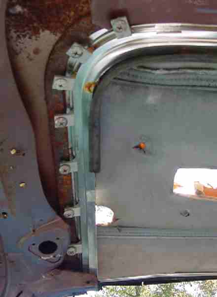
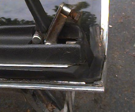
Let's look at how these were installed. This 1978 Trans Am is wearing first design silver frames, which incidentally proves that first design was still being used during 1978 car production. Notice the nice fit at the ends of the frame. You know what holds that against the roof? Nothing!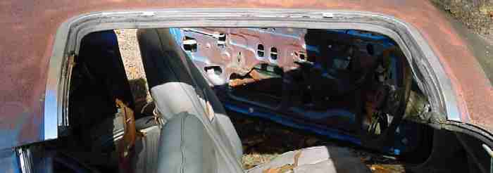
 20 clamps were used on each F-body frame. These were clamped down on a piece of steel bar stock inside the roof. The bar stock was sandwiched between the inner and outer roof in the middle and the back, which greatly increased the rigidity of what was left. In fact, NONE our Hurst-equipped junk cars has the roof caved in, while almost ALL of our Fisher-equipped cars are caved in just behind the t-tops.
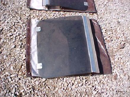
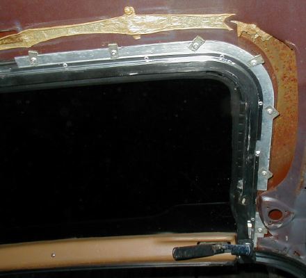
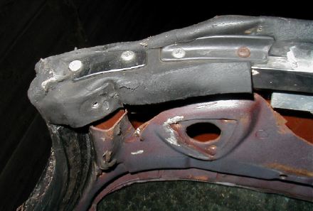
The original inner roof panel had no large holes anywhere. All this was cut away at Hurst. Notice the radical cuts on each end. The installers wanted to leave a little piece of the roof rail, but they hacked away a large area of the inner roof just next to it, apparently to get the last screw in. The radical cuts along the front of the roof (where the sunvisor would be) is because the separation between the roof panels was wide in the front, so you could not pinch the spacer between them.
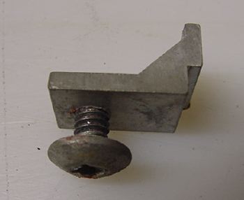
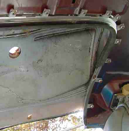
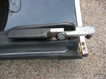
The clip at right is the only kind I have ever seen on a Trans Am. The Hurst manual shows that there was an earlier design, but these may have been used only on G-bodies.
Also, you can see how that bar stock mounted. Notice that it disappears between the roof panels as it bends away from the windshield here.
1rst and 2nd Design Differences
Water leaking was the main reason for the redesign and recall. The 2nd design's major change was a much wider roof weatherstrip. Recalled F-bodies kept their old hatches, but the G-bodies got new hatches with no frame around the glass. The G-body second design went into production on new cars built after December 17, 1976. I have not been able to determine whether or when 2nd design hatches went into production on new Trans Ams.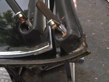
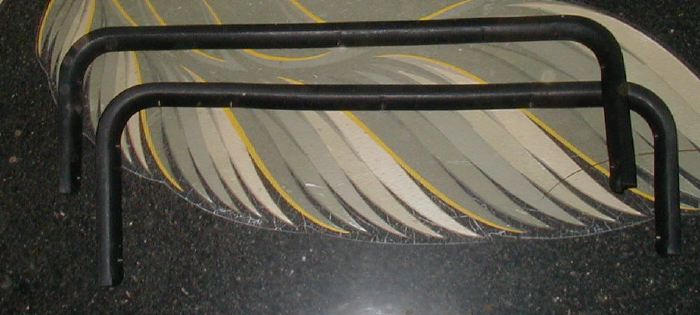
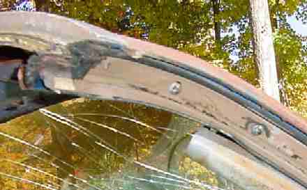
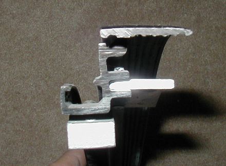
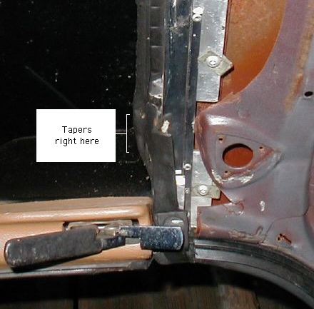
1rst design frame ends depended on what was left of the original roof rail, and didn't have much structure at all. You can also see one of the 1rst design clamps, which weren't used on the 2nd design. They are somewhat prone to get loose from the roof on the end.
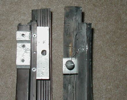
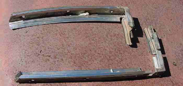
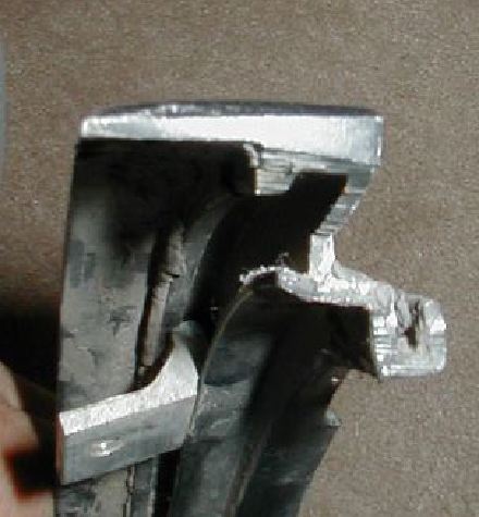
These frames are both aluminum extrusions that were formed into a U-shape that followed the contours of the roof. Part of the extrusion was cut away here on the end. These are obviously hand made and I suppose some hand fitting was required to put them in.
In fact, Jeff at East Coast T-tops told me that when installing Hurst frames, you should position them to match the hatch to the rolled-up window glass. If the frame hangs over, you can grind it off. Don't assume that lining up the edge of the frame to the edge of the roof will fit properly.
2nd design frames installed
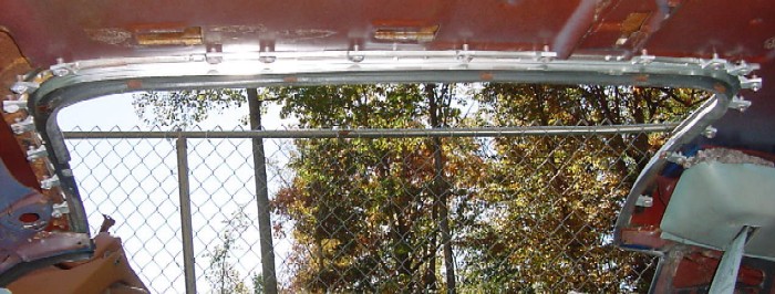
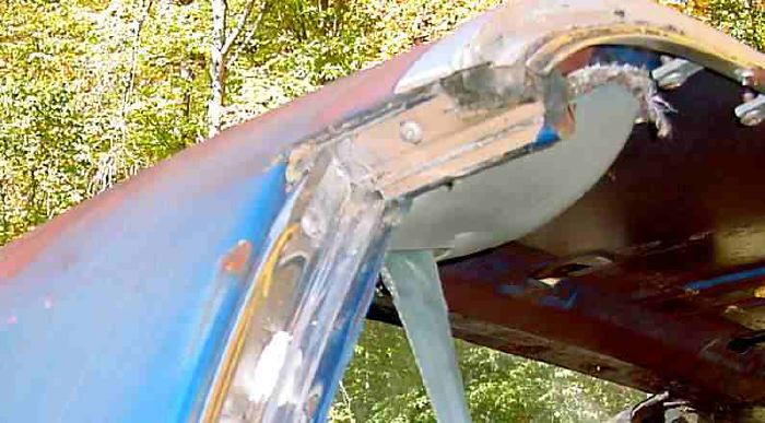
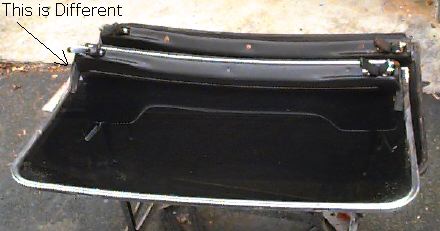
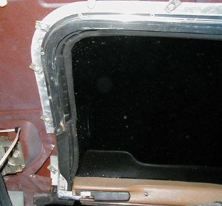
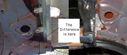
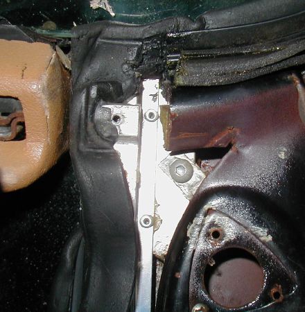
The two photos at right and below show the 2nd frame installed in the car. Roof cutting was almost identical, with the exception that the roof rail was cut away from the corners about an inch. Note the wild gash at the front, which barely leaves metal for the sunvisor attachment.You will note that the hardware used to attach second design frames is totally different. There are no separate clamps. Instead, clamping screws are set in a few long bars riveted to the frame.
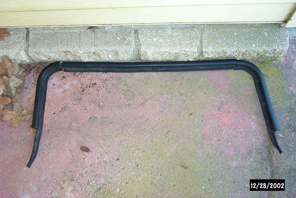
The short molding (below) looks like the long molding with the ends sawed off, but it came that way. The small pieces pictured above are used with the shorter molding. For more details on this version of the molding, see our recall page.