I have seen many variations in these harnesses. Some omitted the fuse, some had built-in jumpers (as shown below on the power supply to the pulse wipers), and there was a combined cruise control and tach wiring harness with only one power supply.
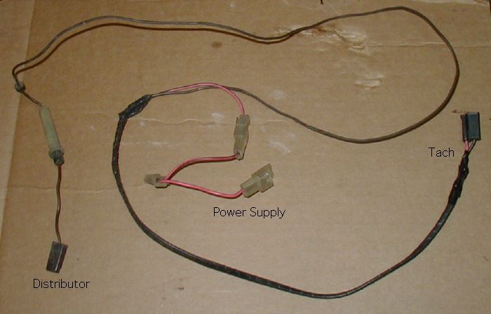
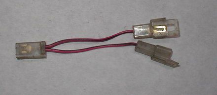
| | The power wire plugged into the spare ignition terminal on the fuse box (see the power windows page). The power window relay and cruise control were also powered off this one terminal, so jumpers like the one at left were required to power two or more of these options. I have seen many variations in these harnesses. Some omitted the fuse, some had built-in jumpers (as shown below on the power supply to the pulse wipers), and there was a combined cruise control and tach wiring harness with only one power supply. |
In 1980 the tach wiring was integrated into the standard harness. We have a 1979 Trans Am built in July, and it also has the tach wiring integrated into the harness, so apparently this was a mid-year change.
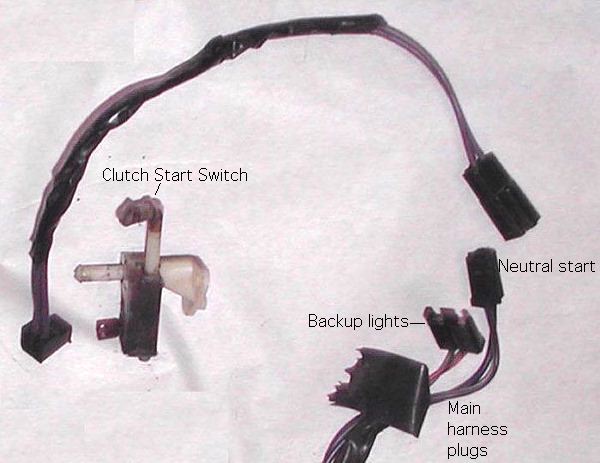
| The cruise control harness gets its power from the spare ignition terminal on the fuse block. It connects the button on the turn signal stalk, a switch on the brake pedal, and the governor on the inner fender. It was taped together with a vacuum hose going to a vacuum breaker on the brake pedal. This was all routed through firewall hole "A". This harness contains a big ball of resistor wire in the circuit that holds the speed setpoint. Some Trans Ams also have cruise control and tach wiring built all in one harness. |
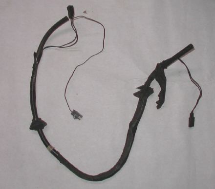 |
 | Wiring for the cruise button, shown here, comes out of a hole at the base of the stalk and is routed through the steering column. | |
There are three versions of this harness:
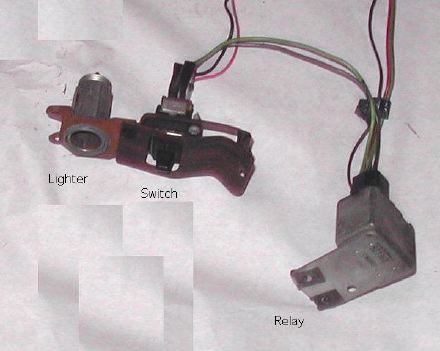
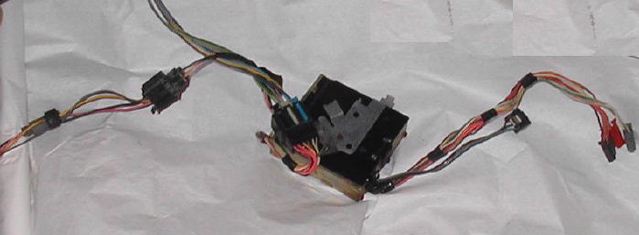
| You can see how three of the components shake out in this nasty photo. I let this one go to the crusher, but I would have kept it if I had realized this is a special harness that powers two options. | 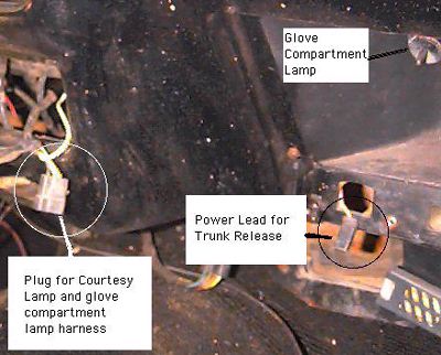 |
Routing of this harness was unusually complicated, and probably not worth trying to duplicate when retrofitting this option. On the driver's side, it is wire-tied to the main instrument panel harness as it crosses the steering column. On the passenger's side, it is routed over the glove compartment in a special wiring tray on the back of the dash pad. This tray has special clips that hold the wires up.
| The trunk lamp was powered by a single wire that plugged into the joint between the rear lamp harness and the wires coming back from the front. I think all years are the same. | 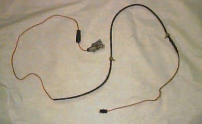 |
Warning Tone GeneratorIn 1981, a warning tone generator was added to the deluxe lamp group. I first saw it on the 1981 build sheets, but I could not find any reference to it in the shop manual. Eventually I removed one. Like so many other things, it is designed to fit the wiring harness as an add-on. The late 70's Firebirds had separate key and seat belt buzzers. The warning tone generator grabs the plugs of both those components, plus it plugs into the console lamp terminal so it'll know if you left your lights on. It has a built in splitter for the console lamp. This is another one of those things that would fit a 77, even though it came out in 1981. | 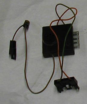 |
Before I describe the A/C harness, I need to at least mention the heater harness for contrast. The IP harness has only one wire that is provided to power the ventilation system. It plugs directly into the heater fan speed switch. The heater harness runs from the fan speed switch to some resistors (under the dash), and then to the fan itself. That's all there is to it.
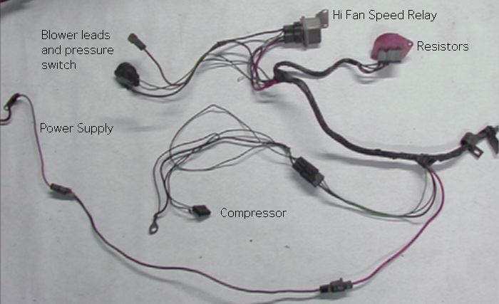
The A/C harness is much more complicated, because it adds the compressor circuit and a special power supply for high fan speed. It takes power from the IP harness for lower fan speeds and the compressor. It has three extensions:
The photo below illustates most of the underhood components of the system. The compressor circuit circuit runs through a pressure and temperature switches before continuing to the compressor harness. The high fan speed relay takes power directly from the alternator to to the blower. When the relay is not energized, power for the fan comes through the resistors.
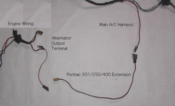
The second power supply for high fan speed is shown below. This extension is for Pontiac engines, which had their alternators on the driver's side.
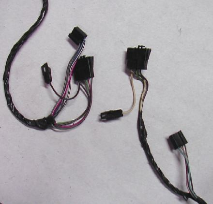 |
The control harness is about one foot long, and separates into two plugs which connect to the compressor switch and the fan speed switch. Earlier Firebirds were wired so that Max A/C always put the fan on high. At some point (probably 1980), this connection was eliminated. The little extra plug connects to the power supply from the I.P. harness. The early harness is shown on the left, and the later harness on the right. |
| This photo shows a closeup of the compressor extension. In addition to turning on the compressor clutch, this harness grounds the whole system through the lug shown and connects to an idle solenoid on the carburetor. For those who don't remember the 70's, the solenoid is supposed to correct the idle speed for the load of the compressor. This is the Pontiac version. On some wimpy underpowered Firebirds this extension also included an extra switch that shut off the A/C at wide open throttle. Chevy-powered cars had the compressor on the wrong side, so a Chevy harness would be much longer. | 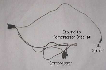 |
Most of the cars we get have the compressors removed. Since the compressor extension grounds the whole thing, it's kind of fun to see what people did to their wiring, after they removed their compressor and found out the fan wouldn't run any more. No two are alike. Go back up and look at the firewall photo showing holes "D" and "E". See those two ground wires above the holes? Do they look original to you?
Pulse Wipers
Pulse (delay) wipers came out in 1978, and featured a harness that added three circuits to the basic wiper system. The switch had 4 terminals that looked like the basic switch, plus another plug that connected to the optional harness. The switch contained only a rheostat in addition to the normal contacts. The electronics to accomplish the delay were all housed in the wiper motor. Many 70's GM cars had separate controller brains for pulse wipers, but Firebirds did not.
The photo shows the inside part of the harness to the left of the grommet, and the under-hood part to the right. The long orange wire is a power supply from the spare battery terminal on the fuse box. It has a built-in piggyback jumper so it doesn't bogart the whole terminal. Because of the way it uses the main harness, I think this could be added to an earlier model Trans Am, but I haven't tried it.
This harness was eliminated in 1980.
Rear Defrost
This is one of the more difficult options to describe. There are basically 4 components to add when installing this option:
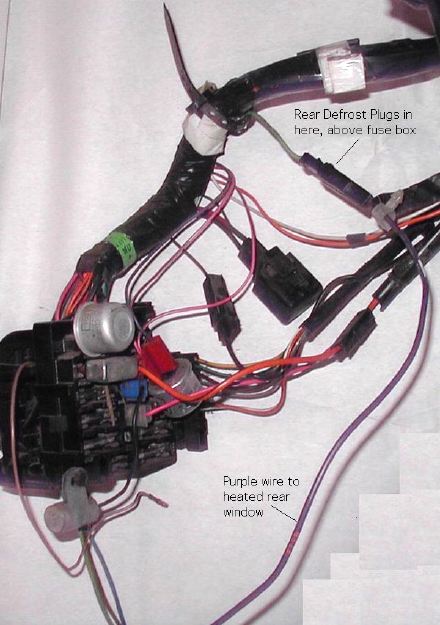
| The switch and timer from 1977 are shown at right. This illustration is really intended to show the plugs in the main I.P. wiring harness. They are connected by short green wires, and located to the right of the A/C controls. I believe that all Firebirds have these plugs, whether you have the rear defrost option or not. If your car does not have these plugs, you'll have to get another I.P. harness to add rear defrost. |
|
|
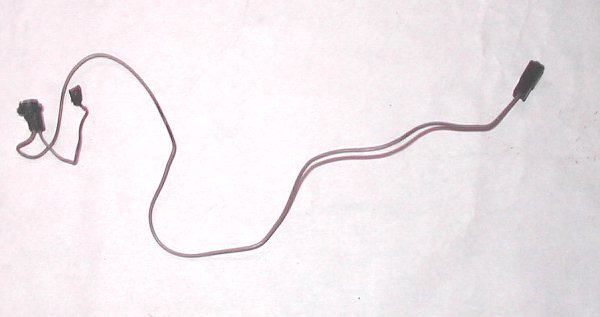
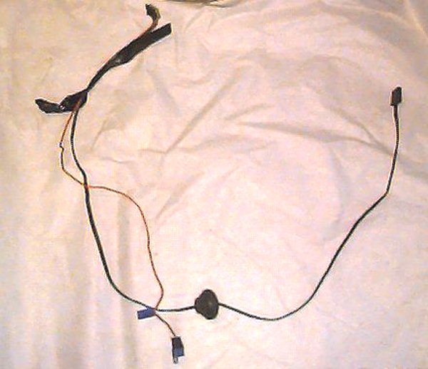
| Power is carried to the rear window by a big purple wire. This wire plugs into an inconspicuous green circuit just above the fuse block. It is routed along the driver's side with the rest of the rear body wiring, and plugs a pigtail on the rear window. |
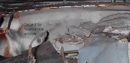
| The rear window is grounded on the passenger's side by a braided ground cable and a screw. The location of this screw is shown here. It's hard to tell what you're looking at, but the blue piece of vinyl is the edge trim on the package shelf. The lower passenger's side corner of the rear window (broken out on this car) is at top left of photo. |
 |
Year to year differences on the rear defrost are confusing and difficult, but (lucky us) I found the technical service button that clears it all up! In mid year 1977, the switch was changed. The old switch had three blades on the passenger side and one on the driver's side. The new one is opposite. The old and new switches look identical from behind, as long as one is right side up and the other is upside down. The plugs will fit, but they're not interchangeable unless you move a couple of wires. Here's the TSB:
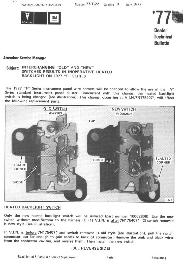
On the back, this continues as follows: "To check for proper operation after installation of the new switch, turn on the ignition. If the green indicator lights, the pink and black wires are reversed. Attempts to turn the switch on or off at this time will damage the switch". It's true. Ask me how I know!
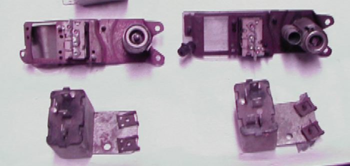
In 1980, the relay/timer grew a new terminal, going from 4 to 5. The back sides of the switch and relay are shown below. Early 1977 is on the left, with 1980 on the right.
Power Windows
Power windows are the subject of a whole 'nuther page.
Power Door Locks
Coming Soon!
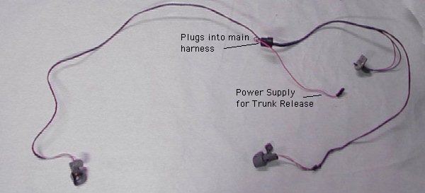
Power Deck Lid Release
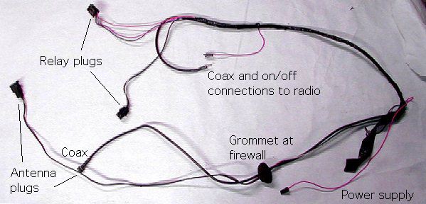
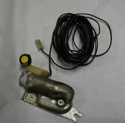 | This is a fairly simple option. It is powered from the courtesy lamp harness, as discussed above. This is routed to the yellow button in the glove compartment, and from there a black wire runs to the solenoid in the trunk. |
| The installed solenoid is shown at right. There is a good article about how to install this option at www.thepontiactransampage.com | 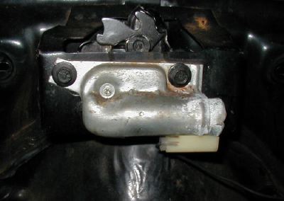 |
The relay plugs got a little sprawled out in the photo, but they both plug into one relay. This view of the back side of the dash pad shows the antenna relay mounted above the glove box and the rear defrost relay mounted on the driver's side edge of the glove box (the right side of this view).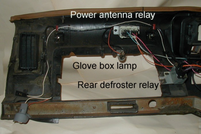
Various Radios, Tape Players, and Stereos
Basic 1970-77 Firebird Radios
| For some reason, Firebirds and Trans Ams used 1960's style radios up to 1977. Trans Ams featured separate console-mounted tape players and single speakers long after the rest of GM had changed. The 70-77 I.P harness only needed two wires to accomodate a radio, for the power and lamp. These are shown in the small plug at right, and also in the I.P. harness photo at the top of this page.
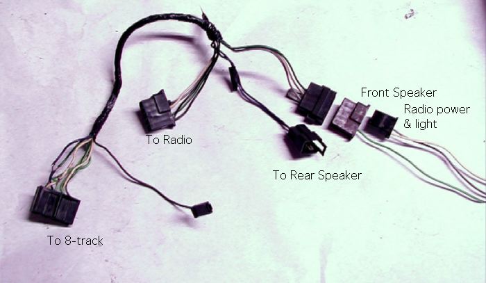
The front speaker used a single green wire (no ground) with a large plug. This plug allowed the IP harness and a rear speaker (if used) to piggyback on it. The rear speaker had two wires (including a ground) which gave a total of 5 wires in this plug. As far as I know the radio was grounded only through its rear brace. | 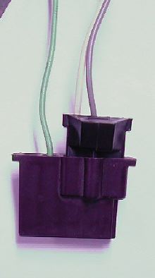 |
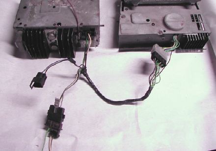 |
Here's a photo that shows the how the harness gets down to business. The radio is on the left, 8-track on the right.
I didn't have a rear speaker wire to plug in when I took this photo. |
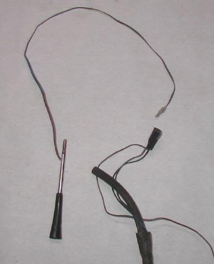
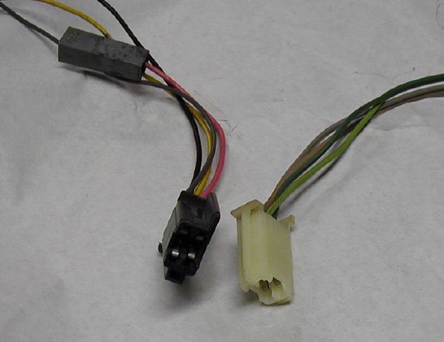
Shown here for illustration are the power plug (left) and the front speaker plug (right). The gray plug at top connects to the power antenna harness.
The amplifier was mounted in the middle of the dash, where the old single front speaker used to be. The amplifier plugs in line between the stereo and the rest of the car. All 12 4-speaker stereo circuits pass trough the amplifier.
In the photo shown here, the amplifier is still plugged into the car and speakers on the left. The 3 plugs on the right would have plugged into the stereo. The shorter wires on the right would have plugged into the "audio boost" switch on a 1980 car, but went nowhere in 1981.
UQ3 Weird File
On the 1980 Indy Pace Car, Pontiac used a toggle switch to turn the amplifier on and off. They also used a toggle switch to dim the turbo boost lights on the hood. Add the switch for rear defrost, and you had too many switches to fit on the instrument panel. This is true of all Indy Pace Cars. In 1981 the audio boost switch was just deleted (the amp was apparently made to work with or without it), and the turbo boost light switch was relocated. So, in 1981, no matter how many options you had, you couldn't get enough toggle switches to fill up the instrument panel. They should have planned better!