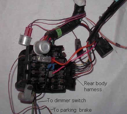
This particular fuse block has power windows connected, which we'll get to later. The add-on wiring harnesses plugged into the middle of the fuse block. Even the radio noise suppression capacitor is made to plug right in.
For some reason most people hate wiring, but I love it, so I'm going to try to reverse engineering it for your benefit. This page describes the layout of the basic wiring harnesses and there is a separate page showing the optional things that could be added to it for each year.
If you had a car with a column shift automatic and no other options, with as much stuff deleted as possible, you'd still need one more major piece, a heater harness, to make a complete car. Every other piece of wiring is related to some type of option, which I hope to document here.
| Four of the five parts of the basic wiring harness are joined at the firewall, forming the fuse block. This figure shows the interior side. The gang of wires plugged in on the right is the body harness, which feeds the taillights. Pontiac called this connector a "harmonica". This is a 1977 fuse block, and it is typical of 1970 to 1979. The 1980 fuse block was totally different and used blade-type fuses.
This particular fuse block has power windows connected, which we'll get to later. The add-on wiring harnesses plugged into the middle of the fuse block. Even the radio noise suppression capacitor is made to plug right in. | |
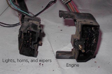 |
The front end harness and engine harnesses snap together to form a square, which plugs through the firewall into the back of the fuse block. The front end wiring is the outboard (driver's side) half, and the engine wiring is the inboard half of the square. It looks like one piece, and it is held to the fuse block by a bolt right in the middle (See B in the firewall photo below). |
So, to summarize, the 1980 and 81 harnesses are each totally uniquie. The 1977-79 harnesses are more similar, but on closer inspection the IP harness is different for each year that I am trying cover.Differences in Basic Harness Components
Two of the five pieces of the basic wiring harness could have some variation. These are the engine harness and the instrument panel harness.Different engine harnesses
There were variations in the engine harness to allow for the many engines in the Firebird lineup. That wasn't a big deal before 1977, but in 1977 all the GM divisions except Cadillac were represented under the Firebird's hood.Different IP harnesses
There were at least two IP harnesses each year, one with rally gages and one without. The fuel gage location is far different for rally vs. standard instruments, so the wiring for the two styles of instruments is totally different. The instrument cluster printed circuits for standard and rally gages are also totally different. The plug for the instruments will physically fit the wrong instrument cluster, but there's hardly a wire on it that'll be in the right place. The wiring diagram shows there may a harness without rear defrost switch wiring, but I have not seen one without it.Year to Year differences
The basic harnesses changed a lot year to year, but sometimes this didn't affect the optional wiring. It should be obvious that the front and rear lamp wiring changed in 1979 when the cars were restyled. Also, the engine harnesses changed as the available engines changed, although wiring for the 301 was the same as a 400.In 1980, the fuse block was totally redesigned, so the 1980-81 harnesses will not mix with the 1970-79. In fact, there were subtle changes to the I.P. harness every year.
- In 1978, I think the style of radio plugs changed, but that is all. Since the radio plugs are usually cut off anyway, the 1978 I.P. harness is pretty much compatible with earlier years.
- In 1979, the dimmer switch was moved from the floor to the steering column, so the I.P. harness had to be revised to accommodate it. This was minor compared to what happened next.
- In 1980, the whole wiring harness was overhauled and the fuse block was changed to blade-type fuses. Almost everything was changed from 1979; there are too many incompatibilities to list.
- In 1981, computer engine controls were used on all GM cars. The 1980 spark control computers had used separate harnesses that didn't connect to anything in the main harness. Although not fully merged, the 1981 computer and instrument panel harnesses connected on 13 circuits, most of which didn't even exist in the 1980 harness.
Note that the wiring to the rear body is in a black conduit. This is routed up and into a tray that Fisher called the "cross-body conduit". This tray spans the width of the firewall and was used by Fisher body to hold power window and door lock wiring. If you did not have either of these options, the tray would be empty to the right of the steering column. In the illustration, the tray contains power window wiring. The single wire parallel to the rear body harness is going to the driver's seat belt.
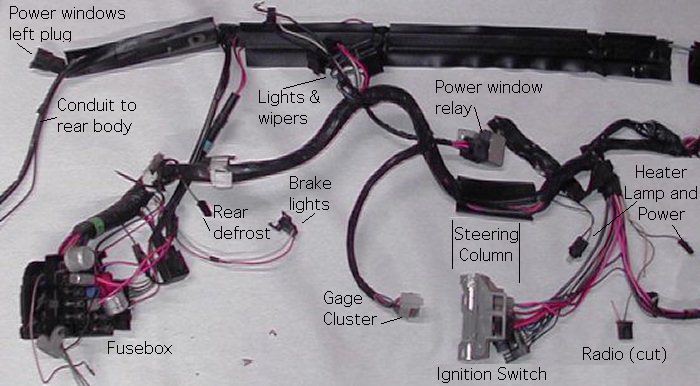
| Here are the fuse block and cross-body conduit actually on the car, showing how the optional wiring runs up to the cross body conduit. This particular car is a 1980 with the blade-type fuses. | 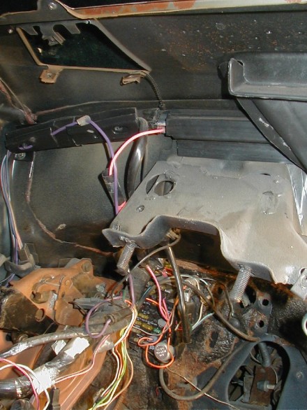 |
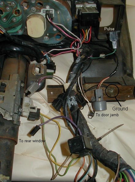 |
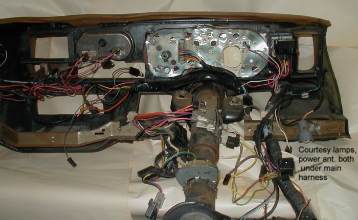
About 1 foot from the fuse block, the I.P. harness is stuffed into a cavity in the dash pad. The Firebird dash pad has a bulge around the instrument panel, and this bulge was designed to act as a conduit below the gauges. In addition to the obvious dimmer, headlight and wiper switches, this part of the harness has connections to the rear window (purple in 1980), driver's seat belt reel switch (black), and driver's door jamb switch (next to the courtesy lamp). In 1980, the harness also had a 2nd brake light switch for the cruise control and a green wire (top) for the rheostat on pulse wipers. The wire tie in the photo is original, and is holding the I.P. harness and power antenna harness together. Also note the ground wire bolted to the dash pad. This example has two lugs connected, one of which is grounds the power antenna. |
Note that there is a major branch of the harness that connects to the steering column, and it is routed away from the removable trim panel. In 1977, there would have been a neutral safety switch here, but in 1979 this was replaced by a mechanical interlock on the steering column.
Immediately after the gages there is a single lamp (2 wires) for the heater controls and a single lamp (1 gray wire) for the side gauge cluster. The heavy brown wire is the power supply for the heater. The heat and a/c wiring has been removed here, as it just gets in the way. Note the green clip on the right. These come in different size to fit different spots on the dash. There are usually two green clips, one on each side of the steering column
Two things added in 1980 are shown. First is an extra idiot light next to the fuel gage (two wires, I think it's an electric choke lamp). Second is an orange and brown pair of wires that fed a digital clock in the top-of-the-line stereo. 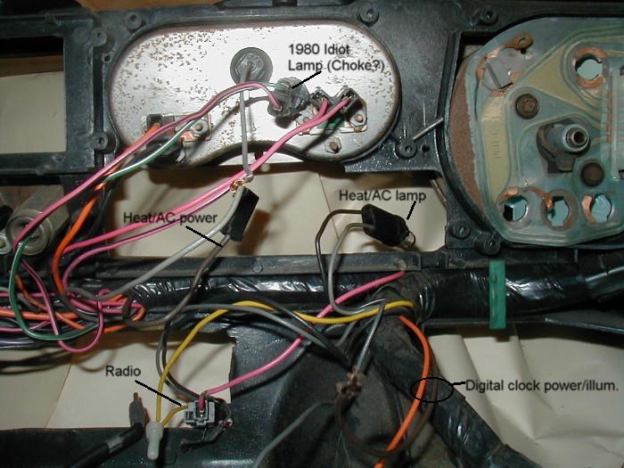
Just above the radio hole the harness tape ends and wires explode out everywhere. This car shows a rear defrost switch and relay installed. All the cars have the wiring for this, so it is just hanging loose if you don't have rear defrost. Note the the antenna cable rolling out from under the harness. Most Firebirds don't have this, because the windshield antenna wire came basically straight down. The last big plug on the harness feeds the interior lamp group and/or trunk lid release. This plug is black and it's obscured in the photo.
The later radio plug shown here has power, ground, and illumination, and a pink up/down signal for the power antenna (it's still connected in the photo). Speaker wiring was separate, and the format was standard 80s GM. A 1970-77 harness would have 1960's radio plug and a plug for a power door lock switch beside the defrost switch.

Finally, we see that everything on the passenger's side was routed over the glove box. The white wire is part of the I.P. harness and connects to the passenger door jamb switch. Optional power antenna and interior lamp group harnesses are installed. Note the red spring clips holding these wires in. There's room for 6 clips, but the usually didn't use very many. Power window, power door lock, and speaker wire was carried o the passenger's side in the cross body conduit.

Shown below is a car with the maximum number (5) of wiring harnesses coming through the firewall. Everything's black in this photo, so it's not easy to see. On the driver's side, the main fuse block is square (B). It has a holes above (A) and below (C). The upper hole (A) was used on earlier Firebirds to carry wiring for the tach, cruise control, and (in 78-79) pulse wipers. You may notice the wiring looks really fat; that's because there is a big rubber hose bound up with the wires. The hose runs to a vacuum breaker that physically kills the cruise control when you step on the brake pedal. The purpose is to get the throttle closed immediately. Just turning off the power to the cruise wouldn't be quick enough.
The lower hole (C) was added to accommodate the power antenna wiring, and as far as I know that's all. Shown is a 1980 car. This grommet carries three wires to make the antenna go up and down, along with the coax to the radio. There were very few cars equipped with this option in 1979, and I've never had one, so I'm not sure if they were exactly the same. Our 1979 junk cars don't have a hint of a hole at (C). There's a close-up on the passenger's side, so skip on down for that.
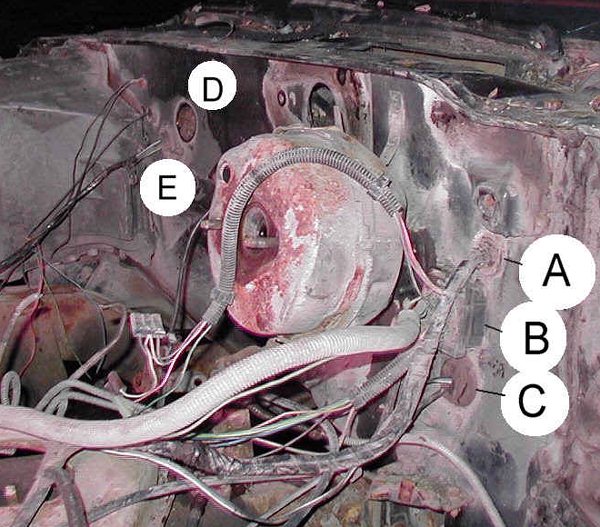
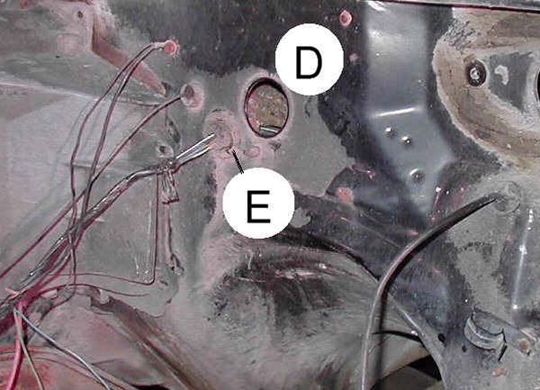
The hole shown here with no wires (D) is for the engine computer harness. This hole was added in 1980 for the electronic spark control used on 301's. This harness had only 7 circuits in it. The 1981 full-blown engine control computer used the same hole for about 50 circuits.
To the left and below the engine control harness hole is the heater and air conditioner harness (E). This particular car has A/C, and the harness is shown in place. Just above the A/C harness is a single tube that supplies vacuum to move the A/C dampers. Cars without A/C don't have this.